Making pulser for corona tests and first results

Note: at any picture you can click and magnify to 1024 x 768 pix


Before begin to build new TEA N2 laser with corona preionization, I feel need for some
test of corona preionizing electrode before make mistake like wrong distance between this
 electrodes and anode, wrong choice of insulators, wrong positions etc.

But, firstly about power supply...

High voltage power supply...
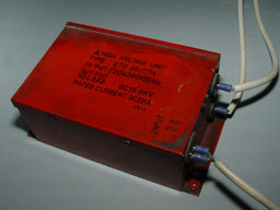
This is currently only one working DC HV power supply which I have and work enough good for most laser and other experiments. It have "only" 15.6 kV, current of 2 mA, but for many applications it is enough. This power supply I was got before few years "for free", which is pulled from photocopier machine. Many other HV supply like "neon sign transformer" with rectifier was burn due to bad current overload protection or because arc between two separate transformer coil  burn it.


I planned use old spark gap (SG) and setup with capacitors which I already have and
mean to use for this, but also you can see what happened with "last test of this SG":
About tesla coil (and how I was burn this SG)

Now, I got better and simplest idea how make simple SG, and how looks making this:

Planning...
Simplifing...
Simple gluing...
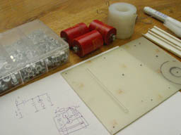
Firstly, write some drawing on paper, use simplest as possible materials, and begin to work.
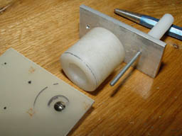
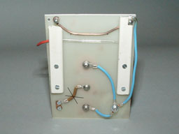
Because pulser for corona tests no need high current during discharge, there no need for making "hard and stable" SG, so I got idea to simple glue elements which you can see at this picture. One PCB without copper, few screws and one simple hollow plastic element (for preventing loud noise - "for any case").
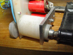
Detail of gluing. At first time I was mean use cyanoacrylate glue, but after half hour, it unglue (Argh!) Then use two component epoxy glue and got enough hard and stable SG.


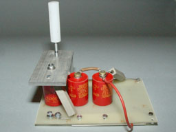
When was finished you can see how it looks simple and nice:

Looks simpe and nice...
Little mistake...
Whole pulser looks simple and nice. I like it. And if it will work as I expect...
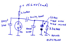
First mistake. Pulser work, but without any effect on preionizing electrode. On picture we can se what is wrong - Instead connection dumping capacitor to SG, I connect it directly to "+" pole of HV power supply. So, this capacitors was charged once and no transfer energy to peaker cap. (later was make correction)
Note: about 3 mm thick wire (curved) is served as anode, and glass tube as preionizing electrode with wire inside. Two piece of white plastic served as holder for preionizing electrode and make different distance from anode.


First test:

First test...
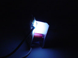
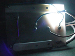
First test in dark...
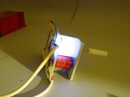
First test of pulsating SG at light. Work OK...
Fist test in dark. Also ok...


Second test:

Blinded camera...
Trick...
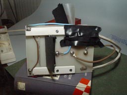
Hmm... too much light from SG blinded my camera, so i need do something. If you carefully look at left side of board, there is very weak corona.
Some patches and now is better (looks less nice, but work) :o) At place where SG make too much light, firstly I was put black paper which cause burning and fire (Perhaps due to too much graphite, or carbon powder in paper). (Sorry, but haven't time to make picture of burning paper or call 911) :o) Later was put there few pieces of insulating tape. It work.


Now it's time for first corona test:

1st diagram...
2nd diagram...
3th diagram...
Something is wrong...
Much better...
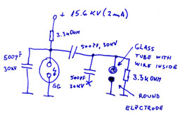
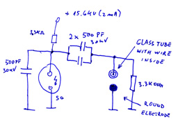
This make another idea that "double" dumping capacitor, and without peaker capacitor. Not any difference in corona discharge light, except SG make more noise. So I give up of this choice.
And, plus, charging resistor of 3K3 become very hot and produce moderately amount of smoke during long test.
Firstly, surprise me that when space between anode and preionizing glass tube is more than zero, there is no corona light.
Above is diagram. Dumping capacitor and peaker capacitor make half of full voltage. So need do something.
When disconnect peaker, it's much better.
Now we can see corona discharge even at dim light in room. (Later pictures will be in totally dark) Now work better because full of 15.6 kV come to preionizing element.


Tis is all folks for now. I don't want to this page become too long. Instead, I will
make another pages with more pictures of corona discharges light. And need
make some more test, so number of picture can be too much.

 BUT!!!

I don't want disappoint you with this page without any "right" pictures, so now my decision
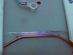
 is put there two the best (until now) of all photos of it:
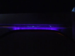
First test results...
First fluorescence test...
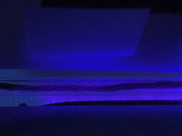
Corona discharge with silver painted glass tube inside. Looks fine.
Corona discharge and fluorescence test with paper without silver paint inside glass tube.

At another page will be explained how to silver paint glass tube inside...