Note: at any picture you can click and magnify to 1024 x 768 pix
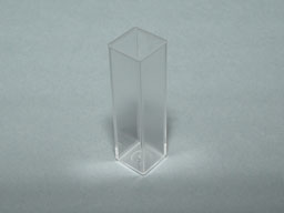
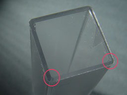
I have only few of this plastic cells, but some of this was destroyed due to
"aggressive" solvent which was sometimes use for disolving dyes. I got this
cells from medical laboratory in town's hospital for "free"...
So, after disappointing with this cells, I was try to found at internet who sell "right" quartz cells.
At some page found it, but with "astronomical" price for my budget (read: empty wallet). Only
choice is build my "own" cell. But there also many problems with founding right materials for this
purpose. Firstly, can't found enough thick plastic, so I was glued two thinner plastic together (this
is also big mistake, because at this place dye leak). Secondly, glass windows was glued
with silicone sealant, which do it's job (glue) moderately good between two glasses, but between
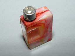
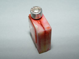
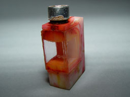
glass and plastic sealant not endure solvent and resulted as leaking dye. See pictures:
 |
 |
| How looks this "miserable
cell"... |
Screw is something like stopper... |
 |
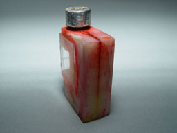 |
| Different angle of view... |
Different angle of view (back
side)... |
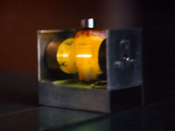
Now, you can see how dye was leak (Mostly, Rhodamine 6G was "painted" this cell)
This is last time that I will make something like this "leaky" cell...
But, however, it is not so "black" with this dye cell. This cell was work moderately well.
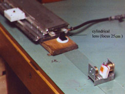
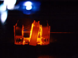
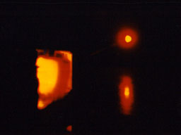
Few next pictures represent how it work. And my apologize for few blurry pictures,
because in this time I make this picture "from hand" without tripod (and with my old film
camera), so result is "out of focus" or "stressed pictures". Now I have good digital camera
and you can see better pictures above (pictures of plastic and "my" dye cell).
